| XC3000 | XC4000E | XC4000X | XC5200 | XC9000 | Spartan | SpartanXL | Virtex |
|---|---|---|---|---|---|---|---|
| Macro | Macro | Macro | Macro | Macro | Macro | Macro | Macro |
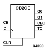
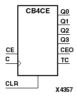
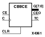
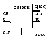
CB2CE, CB4CE, CB8CE, and CB16CE are, respectively, 2-, 4-, 8-, and 16-bit (stage), asynchronous, clearable, cascadable binary counters. The asynchronous clear (CLR) is the highest priority input. When CLR is High, all other inputs are ignored; the Q outputs, terminal count (TC), and clock enable out (CEO) go to logic level zero, independent of clock transitions. The Q outputs increment when the clock enable input (CE) is High during the Low-to-High clock (C) transition. The counter ignores clock transitions when CE is Low. The TC output is High when all Q outputs are High.
Larger counters are created by connecting the CEO output of the first stage to the CE input of the next stage and connecting the C and CLR inputs in parallel. CEO is active (High) when TC and CE are High. The maximum length of the counter is determined by the accumulated CE-to-TC propagation delays versus the clock period. The clock period must be greater than n(tCE-TC), where n is the number of stages and the time tCE-TC is the CE-to-TC propagation delay of each stage. When cascading counters, use the CEO output if the counter uses the CE input; use the TC output if it does not.
The counter is asynchronously cleared, outputs Low, when power is applied. For CPLDs, the power-on condition can be simulated by applying a High-level pulse on the PRLD global net. FPGAs simulate power-on when global reset (GR) or global set/reset (GSR) is active. GR for XC3000 is active-Low. GR for XC5200 and GSR (XC4000, Spartans, Virtex) default to active-High but can be inverted by adding an inverter in front of the GR/GSR input of the STARTUP or STARTUP_VIRTEX symbol.
| Inputs | Outputs | ||||
|---|---|---|---|---|---|
| CLR | CE | C | Qz - Q0 | TC | CEO |
| 1 | X | X | 0 | 0 | 0 |
| 0 | 0 | X | No Chg | No Chg | 0 |
| 0 | 1 | Inc | TC | CEO | |
| z= 1 for CB2CE; z = 3 for CB4CE; z = 7 for CB8CE; z = 15 for CB16CE TC = Qz•Q(z-1)•Q(z-2)•...•Q0 CEO = TC•CE | |||||
Figure 4.1 CB8CE Implementation XC3000, XC4000, XC5200, Spartans, Virtex |
Figure 4.2 CB2CE Implementation XC9000 |
Figure 4.3 CB8CE Implementation XC9000 |