|
|
|
|
|
|
| XC3000 | XC4000E | XC4000X | XC5200 | XC9000 | Spartan | SpartanXL | Spartan2 | Virtex |
|---|---|---|---|---|---|---|---|---|
| N/A | N/A | N/A | N/A | N/A | N/A | N/A | Primitive | Primitive |

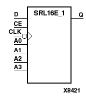
SRL16E_1 is a shift register look up table (LUT) with clock enable (CE). The inputs A3, A2, A1, and A0 select the output length of the shift register. The shift register may be of a fixed, static length or dynamically adjusted. Refer to “Static Length Mode” and “Dynamic Length Mode” in the "SRL16" section.
The shift register LUT contents are initialized by assigning a four-digit hexadecimal number to an INIT attribute. The first, or the left-most, hexadecimal digit is the most significant bit. If an INIT value is not specified, it defaults to a value of four zeros (0000) so that the shift register LUT is cleared during configuration.
When CE is High, the data (D) is loaded into the first bit of the shift register during the High-to-Low clock (CLK) transition. During subsequent High-to-Low clock transitions, when CE is High, data is shifted to the next highest bit position as new data is loaded. The data appears on the Q output when the shift register length determined by the address inputs is reached.
When CE is Low, the register ignores clock transitions.
| Inputs | Output | ||||
|---|---|---|---|---|---|
| CE | CLK | D | <SR(1)> | <SR(i)> | Q |
| 0 | X | X | No Chg | No Chg | No Chg |
| 1 | 1 | X | No Chg | No Chg | No Chg |
| 1 | 0 | X | No Chg | No Chg | No Chg |
| 1 | D | D | SR(i-1) | SR(L) | |
| SR(1) = contents of first shift register SR(i) = contents of the i'th shift register stage (2<= n <= L) L = shift register length (1 through 16 determined by (8*A3) +(4*A2) + (2*A1) + A0 +1) | |||||