|
|
|
|
|
|
| XC3000 | XC4000E | XC4000X | XC5200 | XC9000 | Spartan | SpartanXL | Spartan2 | Virtex |
|---|---|---|---|---|---|---|---|---|
| N/A | Primitive | Primitive | Primitive | N/A | Primitive | Primitive | N/A | N/A |
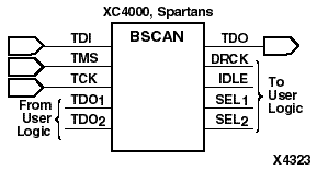
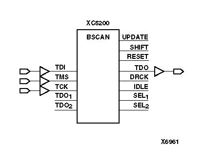
The BSCAN symbol indicates that boundary scan logic should be enabled after the programmable logic device (PLD) configuration is complete. It also provides optional access to some special features of the XC5200 boundary scan logic.
Note: For specific information on boundary scan for each architecture, refer to The Programmable Logic Data Book.
To indicate that boundary scan remains enabled after configuration, connect the BSCAN symbol to the TDI, TMS, TCK, and TDO pads. The other pins on BSCAN do not need to be connected, unless those special functions are needed. A signal on the TDO1 input is passed to the external TDO output when the USER1 instruction is executed; the SEL1 output goes High to indicate that the USER1 instruction is active. The TDO2 and SEL2 pins perform a similar function for the USER2 instruction. The DRCK output provides access to the data register clock (generated by the TAP controller). The IDLE output provides access to a version of the TCK input, which is only active while the TAP controller is in the Run-Test-Idle state. The RESET, UPDATE, and SHIFT pins of the XC5200 BSCAN symbol represent the decoding of the corresponding state of the boundary scan internal state machine. These functions are not available in the XC4000E, XC4000X, Spartan, and SpartanXL.
If boundary scan is used only before configuration is complete, do not include the BSCAN symbol in the design. The TDI, TMS, TCK, and TDO pins can be reserved for user functions.