|
|
|
|
|
|
| XC3000 | XC4000E | XC4000X | XC5200 | XC9000 | Spartan | SpartanXL | Spartan2 | Virtex |
|---|---|---|---|---|---|---|---|---|
| Macro | Macro | Macro | Macro | Macro | Macro | Macro | Macro | Macro |
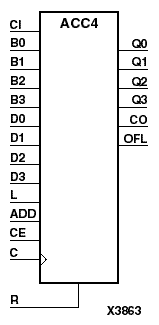
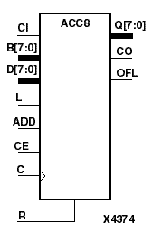
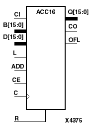
ACC4, ACC8, ACC16 can add or subtract a 4-, 8-, 16-bit unsigned-binary, respectively or twos-complement word to or from the contents of a 4-, 8-, 16-bit data register and store the results in the register. The register can be loaded with the 4-, 8-, 16-bit word.
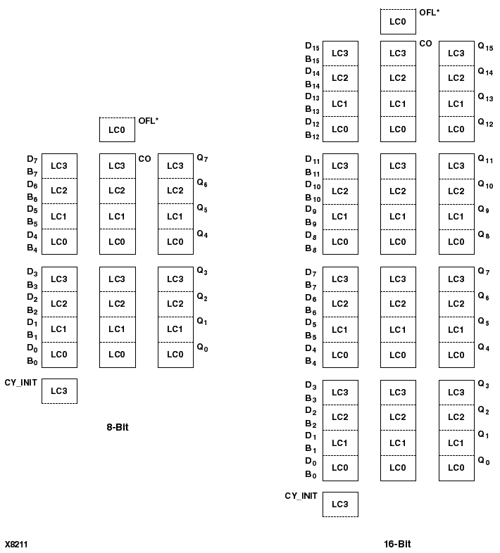
In the XC4000, Spartan, and SpartanXL, these accumulators are implemented using carry logic and relative location constraints, which assure most efficient logic placement.
The synchronous reset (R) has priority over all other inputs, and when High, causes all outputs to go to logic level zero during the Low-to-High clock (C) transition. Clock (C) transitions are ignored when clock enable (CE) is Low.
The accumulator is asynchronously cleared, outputs Low, when power is applied. For CPLDs, the power-on condition can be simulated by applying a High-level pulse on the PRLD global net. FPGAs simulate power-on when global reset (GR) or global set/reset (GSR) is active. GR for XC3000 is active-Low. GR for XC5200 and GSR (XC4000, Spartans, Virtex) default to active-High but can be inverted by adding an inverter in front of the GR/GSR input of the STARTUP, STARTUP_SPARTAN2, or STARTUP_VIRTEX symbol.
When the load input (L) is High, CE is ignored and the data on the D inputs is loaded into the register during the Low-to-High clock (C) transition. ACC4 loads the data on inputs D3 - D0 into the 4-bit register. ACC8 loads the data on D7 - D0 into the 8-bit register. ACC16 loads the data on inputs D15 - D0 into the 16-bit register.
ACC4, ACC8, ACC16 can operate, respectively, on either 4-, 8-, 16-bit unsigned binary numbers or 4-, 8-, 16-bit twos-complement numbers. If the inputs are interpreted as unsigned binary, the result can be interpreted as unsigned binary. If the inputs are interpreted as twos complement, the output can be interpreted as twos complement. The only functional difference between an unsigned binary operation and a twos-complement operation is how they determine when “overflow” occurs. Unsigned binary uses CO, while twos complement uses OFL to determine when “overflow” occurs.
For unsigned binary operation, ACC4 can represent numbers between 0 and 15, inclusive; ACC8 between 0 and 255, inclusive; and ACC16 between 0 and 65535, inclusive. In add mode, CO is active (High) when the sum exceeds the bounds of the adder/subtracter. In subtract mode, CO is an active-Low borrow-out and goes Low when the difference exceeds the bounds. The carry-out (CO) is not registered synchronously with the data outputs. CO always reflects the accumulation of the B inputs (B3 - B0 for ACC4, B7 - B0 for ACC8, B15 - B0 for ACC16) and the contents of the register. This allows cascading of ACC4s, ACC8s, or ACC16s by connecting CO of one stage to CI of the next stage. An unsigned binary “overflow” that is always active-High can be generated by gating the ADD signal and CO as follows.
unsigned overflow = CO XOR ADD
OFL should be ignored in unsigned binary operation.
For twos-complement operation, ACC4 can represent numbers between -8 and +7, inclusive; ACC8 between -128 and +127, inclusive; ACC16 between -32768 and +32767, inclusive. If an addition or subtraction operation result exceeds this range, the OFL output goes High. The overflow (OFL) is not registered synchronously with the data outputs. OFL always reflects the accumulation of the B inputs (B3 - B0 for ACC4, B7 - B0 for ACC8, B15 - B0 for ACC16) and the contents of the register, which allows cascading of ACC4s, ACC8s, or ACC16s by connecting OFL of one stage to CI of the next stage.
CO should be ignored in twos-complement operation.
This is the ACC4 (4-bit), ACC8 (8-bit), and ACC16 (16-bit) topology for XC4000E, XC4000X, Spartan, and SpartanXL devices.
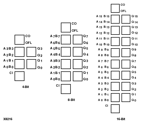
This is the ACC8 (8-bit) and ACC16 (16-bit) topology for XC5200 devices.
