|
|
|
|
|
|
| XC3000 | XC4000E | XC4000X | XC5200 | XC9000 | Spartan | SpartanXL | Spartan2 | Virtex |
|---|---|---|---|---|---|---|---|---|
| N/A | N/A | N/A | N/A | Macro | N/A | N/A | N/A | N/A |


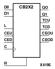
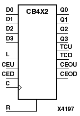
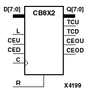
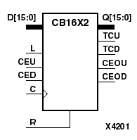
CB2X2, CB4X2, CB8X2, and CB16X2 are, respectively, 2-, 4-, 8-, and 16-bit (stage), synchronous, loadable, resettable, bidirectional binary counters. These counters have separate count-enable inputs and synchronous terminal-count outputs for up and down directions to support high-speed cascading in the CPLD architecture.
The synchronous reset (R) is the highest priority input. When R is High, all other inputs are ignored; the data outputs (Q) go to logic level zero, terminal count outputs TCU and TCD go to zero and one, respectively, and clock enable outputs CEOU and CEOD go to Low and High, respectively, on the Low-to-High clock (C) transition. The data on the D inputs loads into the counter on the Low-to-High clock (C) transition when the load enable input (L) is High, independent of the CE inputs.
All Q outputs increment when CEU is High, provided R and L are Low during the Low-to-High clock transition. All Q outputs decrement when CED is High, provided R and L are Low. The counter ignores clock transitions when CEU and CED are Low. Both CEU and CED should not be High during the same clock transition; the CEOU and CEOD outputs might not function properly for cascading when CEU and CED are both High.
For counting up, the CEOU output is High when all Q outputs and CEU are High. For counting down, the CEOD output is High when all Q outputs are Low and CED is High. To cascade counters, the CEOU and CEOD outputs of each counter are, respectively, connected directly to the CEU and CED inputs of the next stage. The C, L, and R inputs are connected in parallel.
In Xilinx CPLD devices, the maximum clocking frequency of these counter components is unaffected by the number of cascaded stages for all counting and loading functions. The TCU terminal count output is High when all Q outputs are High, regardless of CEU. The TCD output is High when all Q outputs are Low, regardless of CED.
When cascading counters, the final terminal count signals can be produced by AND wiring all the TCU outputs (for the up direction) and all the TCD outputs (for the down direction). The TCU, CEOU, and CEOD outputs are produced by optimizable AND gates within the component. This results in zero propagation from the CEU and CED inputs and from the Q outputs, provided all connections from each such output remain on-chip. Otherwise, a macrocell buffer delay is introduced.
The counter is initialized to zero (TCU Low and TCD High) when power is applied. For CPLDs, the power-on condition can be simulated by applying a High-level pulse on the PRLD global net.
| Inputs | Outputs | |||||||||
|---|---|---|---|---|---|---|---|---|---|---|
| R | L | CEU | CED | C | Dz - D0 | Qz - Q0 | TCU | TCD | CEOU | CEOD |
| 1 | X | X | X | X | 0 | 0 | 1 | 0 | CEOD | |
| 0 | 1 | X | X | Dn | dn | TCU | TCD | CEOU | CEOD | |
| 0 | 0 | 0 | 0 | X | X | No Chg | No Chg | No Chg | 0 | 0 |
| 0 | 0 | 1 | 0 | X | Inc | TCU | TCD | CEOU | 0 | |
| 0 | 0 | 0 | 1 | X | Dec | TCU | TCD | 0 | CEOD | |
| 0 | 0 | 1 | 1 | X | Inc | TCU | TCD | Invalid | Invalid | |
| z = 1 for CB2X2; z = 3 for CB4X2; z = 7 for CB8X2; z = 15 for CB16X2 d = state of referenced input (Dn) one setup time prior to active clock transition TCU = Qz•Q(z-1)•Q(z-2)•...•Q0 TCD = !Qz•!Q(z-1)•!Q(z-2)•...•!Q0 CEOU = TCU•CEU CEOD = TCD•CED | ||||||||||