|
|
|
|
|
|
| XC3000 | XC4000E | XC4000X | XC5200 | XC9000 | Spartan | SpartanXL | Spartan2 | Virtex |
|---|---|---|---|---|---|---|---|---|
| Primitive | Primitive | Primitive | Primitive | Primitive | Primitive | Primitive | Primitive | Primitive |

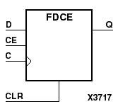
FDCE is a single D-type flip-flop with clock enable and asynchronous clear. When clock enable (CE) is High and asynchronous clear (CLR) is Low, the data on the data input (D) of FDCE is transferred to the corresponding data output (Q) during the Low-to-High clock (C) transition. When CLR is High, it overrides all other inputs and resets the data output (Q) Low. When CE is Low, clock transitions are ignored.
The flip-flop is asynchronously cleared, output Low, when power is applied. For CPLDs, the power-on condition can be simulated by applying a High-level pulse on the PRLD global net. FPGAs simulate power-on when global reset (GR) or global set/reset (GSR) is active. GR for XC3000 is active-Low. GR for XC5200 and GSR (XC4000, Spartans, Virtex) default to active-High but can be inverted by adding an inverter in front of the GR/GSR input of the STARTUP, STARTUP_SPARTAN2, or STARTUP_VIRTEX symbol.
For XC9500XL and XC9500XV devices, logic connected to the clock enable (CE) input may be implemented using the clock enable product term (p-term) in the macrocell, provided the logic can be completely implemented using the single p-term available for clock enable without requiring feedback from another macrocell. Only FDCE and FDPE flip-flops primitives may take advantage of the clock-enable p-term.
| Inputs | Outputs | |||
|---|---|---|---|---|
| CLR | CE | D | C | Q |
| 1 | X | X | X | 0 |
| 0 | 0 | X | X | No Chg |
| 0 | 1 | 1 | 1 | |
| 0 | 1 | 0 | 0 | |