|
|
|
|
|
|
| XC3000 | XC4000E | XC4000X | XC5200 | XC9000 | Spartan | SpartanXL | Spartan2 | Virtex |
|---|---|---|---|---|---|---|---|---|
| N/A | Primitive | Primitive | Primitive | N/A | Primitive | Primitive | Primitive | Primitive |

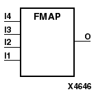
The FMAP symbol is used to control logic partitioning into XC4000 4-input function generators. For XC4000, Spartan, and SpartanXL, the place and route software chooses an F or a G function generator as a default, unless you specify an F or G. The FMAP symbol is used in an XC5200, a Virtex, or a Spartan2 device to map logic to the function generator of a slice. Refer to the appropriate CAE tool interface user guide for information about specifying this attribute in your schematic design editor.
For the XC4000, Spartan, and SpartanXL devices, the FMAP symbol is usually used with the HMAP symbol, which partitions logic into the 3-input generator of the Configurable Logic Block (CLB). You can implement a portion of logic using gates, latches, and flip-flops and specify the logic to be grouped into F, G, and H function generators by naming logic signals and FMAP/HMAP signals correspondingly. These symbols are used for mapping control in addition to the actual gates, latches, and flip-flops, not as a substitute for them.
The following figure gives an example of how logic can be placed using FMAP and HMAP symbols.
The MAP=type parameter can be used with the FMAP symbol to further define how much latitude you want to give the mapping program. The following table shows MAP option characters and their meanings.
| MAP Option Character | Function |
|---|---|
| P | Pins. |
| C | Closed - Adding logic to or removing logic from the CLB is not allowed. |
| L | Locked - Locking CLB pins. |
| O | Open - Adding logic to or removing logic from the CLB is allowed. |
| U | Unlocked - No locking on CLB pins. |
Possible types of MAP parameters for FMAP are MAP=PUC, MAP=PLC, MAP=PLO, and MAP=PUO. The default parameter is PUO. If one of the “open” parameters is used (PLO or PUO), only the output signals must be specified.
Note: Currently, only PUC and PUO are observed. PLC and PLO are translated into PUC and PUO, respectively.
The FMAP symbol can be assigned to specific CLB locations using LOC attributes. Refer to the “Mapping Constraint Examples” section of the “Attributes, Constraints, and Carry Logic” chapter and to the appropriate CAE tool interface user guide for more information on assigning LOC attributes.