|
|
|
|
|
|
| Element | XC3000 | XC4000E | XC4000X | XC5200 | XC9000 | Spartan | SpartanXL | Spartan2 | Virtex |
|---|---|---|---|---|---|---|---|---|---|
| ILD | Primitive | Macro | Macro | Macro | Macro | Macro | Macro | Macro | Macro |
| ILD4, ILD8, ILD16 | Macro | Macro | Macro | Macro | Macro | Macro | Macro | Macro | Macro |


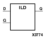
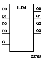
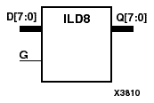
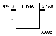
ILD, ILD4, ILD8, and ILD16 are single or multiple transparent data latches, which can be used to hold transient data entering a chip. The ILD latch is contained in an input/output block (IOB), except for XC5200 and XC9000. The latch input (D) is connected to an IPAD or an IOPAD (without using an IBUF). When the gate input (G) is High, data on the inputs (D) appears on the outputs (Q). Data on the D inputs during the High-to-Low G transition is stored in the latch.
The latch is asynchronously cleared with Low output when power is applied. For CPLDs, the power-on condition can be simulated by applying a High-level pulse on the PRLD global net. FPGAs simulate power-on when global reset (GR) or global set/reset (GSR) is active. GR for XC3000 is active-Low. GR for XC5200 and GSR (XC4000, Spartans, Virtex) default to active-High but can be inverted by adding an inverter in front of the GR/GSR input of the STARTUP, STARTUP_SPARTAN2, or STARTUP_VIRTEX symbol.
The XC3000 ILD is actually the input flip-flop master latch. If both ILD and IFD elements are controlled by the same clock signal, the relationship between the transparent sense of the latch and the active edge of the flip-flop is fixed as follows: a transparent High latch (ILD) corresponds to a falling edge-triggered flip-flop (IFD_1), and a transparent Low latch (ILD_1) corresponds to a rising edge-triggered flip-flop (IFD). Because the place and route software does not support using both phases of a clock for IOBs on a single edge of the device, certain combinations of ILD and IFD elements are not allowed.
Refer to the following figure for legal IFD, IFD_1, ILD, and ILD_1 combinations for the XC3000.
In XC4000, Spartan, and SpartanXL, the ILD is actually the input flip-flop master latch. It is possible to access two different outputs from the input flip-flop: one that responds to the level of the clock signal and another that responds to an edge of the clock signal. When using both outputs from the same input flip-flop, a transparent High latch (ILD) corresponds to a falling edge-triggered flip-flop (IFD_1). Similarly, a transparent Low latch (ILD_1) corresponds to a rising edge-triggered flip-flop (IFD).
Refer to the following figure for legal IFD, IFD_1, ILD, and ILD_1 combinations for the XC4000, Spartan, and SpartanXL.
| Inputs | Outputs | |
|---|---|---|
| G | D | Q |
| 1 | 1 | 1 |
| 1 | 0 | 0 |
| 0 | X | d |
| d = state of referenced input one setup time prior to active G transition | ||