Libraries GuideChapter 11: Design Elements (X74_42 to X74_521)
X74_195
4-Bit Loadable Serial/Parallel-In Parallel-Out Shift Register
XC3000
| XC4000E
| XC4000X
| XC5200
| XC9000
| Spartan
| SpartanXL
| Spartan2
| Virtex
|
|---|
Macro
| Macro
| Macro
| Macro
| Macro
| Macro
| Macro
| N/A
| N/A
|

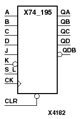
X74_195 is a 4-bit shift register with shift-right serial inputs (J, active High, and K, active Low), parallel inputs (D - A), parallel outputs (QD - QA) and QDB, shift/load control input (S_L), and active-Low asynchronous clear (CLR). Asynchronous CLR, when Low, overrides all other inputs and resets data outputs QD - QA Low and QDB High. When S_L is Low and CLR is High, data on the D - A inputs is loaded into the corresponding QD - QA bits of the register during the Low-to-High clock (CK) transition. When S_L and CLR are High, the first bit of the register (QA) responds to the J and K inputs during the Low-to-High clock transition, as shown in the truth table. During subsequent Low-to-High clock transitions, with S_L and CLR High, the data is shifted to the next-highest bit position (shift right) as new data is loaded into QA (J, K QA, QA
 QB, QB
 QC, and so forth).
Registers can be cascaded by connecting the QD and QDB outputs of one stage to the J and K inputs, respectively, of the next stage and connecting clock, S_L and CLR inputs in parallel.
Inputs
| Outputs
|
|---|
CLR
| S_L
| J
| K
| A - D
| CK
| QA
| QB
| QC
| QD
| QDB
|
|---|
0
| X
| X
| X
| X
| X
| 0
| 0
| 0
| 0
| 1
|
1
| 0
| X
| X
| A - D
| 
| a
| b
| c
| d
| !d
|
1
| 1
| 0
| 0
| X
| 
| 0
| qa
| qb
| qc
| !qc
|
1
| 1
| 1
| 1
| X
| 
| 1
| qa
| qb
| qc
| !qc
|
1
| 1
| 0
| 1
| X
| 
| qa
| qa
| qb
| qc
| !qc
|
1
| 1
| 1
| 0
| X
| 
| !qa
| qa
| qb
| qc
| !qc
|
Lowercase letters represent state of referenced input or output one setup time prior to active clock transition
|

![]() QA, QA
QA, QA![]() QB, QB
QB, QB![]() QC, and so forth).
QC, and so forth).