|
|
|
|
|
|
All counter, register, and storage functions are derived from the flip-flops (and latches in XC4000X and SpartanXL) available in the Configurable Logic Blocks (CLBs).
The D flip-flop is the basic building block for all architectures. Differences occur from the availability of asynchronous Clear (CLR) and Preset (PRE) inputs, and the source of the synchronous control signals, such as, Clock Enable (CE), Clock (C), Load enable (L), synchronous Reset (R), and synchronous Set (S). The basic flip-flop configuration for each architecture follows.
The XC3000 and XC5200 have a direct-connect Clock Enable input and a Clear input.
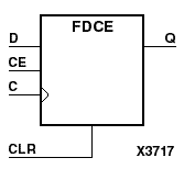
The XC4000s, XC9500XL, Spartan, and SpartanXL have a direct-connect Clock Enable input and a choice of either the Clear or the Preset inputs, but not both.
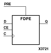

The basic XC9000 flip-flops have both Clear and Preset inputs.
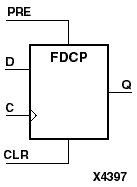
Virtex and Spartan2 have two basic flip-flop types. One has both Clear and Preset inputs and one has both asynchronous and synchronous control functions.
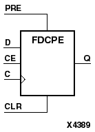
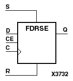
The asynchronous and synchronous control functions, when used, have a priority that is consistent across all devices and architectures. These inputs can be either active-High or active-Low as defined by the macro. The priority, from highest to lowest is as follows.
Note: The asynchronous CLR and PRE inputs, by definition, have priority over all the synchronous control and clock inputs.
For FPGA families, the Clock Enable (CE) function is implemented using two different methods in the Xilinx Unified Libraries; both are shown in the “Clock Enable Implementation Methods” figure.
The method used in a particular macro is indicated by the inclusion of asynchronous clear, asynchronous preset, synchronous set, or synchronous reset in the macro's description.