|
|
|
|
|
|
| XC3000 | XC4000E | XC4000X | XC5200 | XC9000 | Spartan | SpartanXL | Spartan2 | Virtex |
|---|---|---|---|---|---|---|---|---|
| Primitive | N/A | N/A | N/A | N/A | N/A | N/A | N/A | N/A |

The CLB symbol enables you to manually specify a CLB configuration. It allows you to enter portions of a logic design directly in terms of the physical CLB, rather than schematically. Using the CLB symbol provides precise partitioning control and requires knowledge of the CLB architecture. Use it in place of the equivalent captured logic and not in conjunction with it.
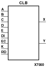
A blank XC3000 CLB primitive symbol and its corresponding configured CLB primitive and circuit are shown in the following figure.
CLB symbol pins correspond to actual CLB pins. Signals connected to these pins in a schematic are connected to the corresponding CLB pins in the design. You must specify the BASE, CONFIG, EQUATE_F, and EQUATE_G commands for the CLB. It is not necessary for the translator program to parse the commands specifying the CLB configuration. The mapping program from the LCA Xilinx netlist to the LCA design checks these commands for errors.
The configuration commands must be consistent with the connections. For example, if you use the A input in an equation, connect a signal to the A pin. Refer to the applicable CAE tool interface user guide for more information on specifying the CLB configuration commands in the schematic.
You can specify the location of a CLB on the device using the LOC attribute. When specifying the LOC attribute, a valid CLB name (AA, AB, and so forth) must be used. Refer to the “LOC” section of the “Attributes, Constraints, and Carry Logic” chapter for more information.