|
|
|
|
|
|
| XC3000 | XC4000E | XC4000X | XC5200 | XC9000 | Spartan | SpartanXL | Spartan2 | Virtex |
|---|---|---|---|---|---|---|---|---|
| N/A | N/A | N/A | N/A | N/A | N/A | N/A | Primitive | Primitive |
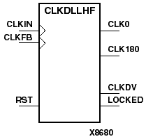
CLKDLLHF is a high frequency clock delay locked loop used to minimize clock skew. CLKDLLHF synchronizes the clock signal at the feed back clock input (CLKFB) to the clock signal at the input clock (CLKIN). The locked output (LOCKED) is high when the two signals are in phase. The signals are considered to be in phase when their rising edges are within 250 ps of each other.
The frequency of the clock signal at the CLKIN input must be in the range 60 - 180 MHz. The CLKIN pin must be driven by an IBUFG or a BUFG.
On-chip synchronization is achieved by connecting the CLKFB input to a point on the global clock network driven by a BUFG, a global clock buffer. The BUFG input can only be connected to the CLK0 output of CLKDLLHF. The BUFG connected to the CLKFB input of the CLKDLLHF must be sourced from the CLK0 output of the same CLKDLLHF. The CLKIN input should be connected to the output of an IBUFG, with the IBUFG input connected to a pad driven by the system clock.
Off-chip synchronization is achieved by connecting the CLKFB input to the output of an IBUFG, with the IBUFG input connected to a pad. Only the CLK0 output can be used. CLK0 must be connected to the input of OBUF, an output buffer.
The duty cycle of the CLK0 output is 50-50 unless the DUTY_CYCLE_CORRECTION attribute is set to FALSE, in which case the duty cycle is the same as that of the CLKIN input. The duty cycle of the phase shifted output (CLK180) is the same as that of the CLK0 output. The frequency of the CLKDV output is determined by the value assigned to the CLKDV_DIVIDE attribute.
The master reset input (RST) resets CLKDLL to its initial (power-on) state. The signal at the RST input is synchronized to the clock signal at the CLKIN input. The reset becomes effective at the second Low-to-High transition of the clock signal at the CLKIN input after assertion of the RST signal.
| Output | Description |
|---|---|
| CLK0 | Clock at 1x CLKIN frequency |
| CLK180 | Clock at 1x CLKIN frequency, shifted 180o with regards to CLK0 |
| CLKDV | Clock at (1/n)x CLKIN frequency, n=CLKDV_DIVIDE value |
| LOCKED | CLKDLL locked |
Note: Refer to the “PERIOD Specifications on CLKDLLs” section of the "Using Timing Constraints" chapter in the Development System Reference Guide for additional information on using the TNM, TNM_NET, and PERIOD attributes with CLKDLLHF components.