|
|
|
|
|
|
| XC3000 | XC4000E | XC4000X | XC5200 | XC9000 | Spartan | SpartanXL | Spartan2 | Virtex |
|---|---|---|---|---|---|---|---|---|
| N/A | N/A | N/A | Primitive | N/A | N/A | N/A | N/A | N/A |

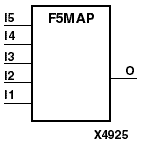
The F5MAP symbol is used to control the logic partitioning of 5-input functions into the top or bottom half of a CLB. The F5MAP symbol is not a substitute for logic. It is used in addition to combinatorial gates for mapping control.
At the schematic level, any 5-input logic function can be implemented using gates and mapped into half of a single CLB by using the F5MAP symbol. The signals that are the inputs and outputs of the 5-input function must be labelled and connected to appropriate pins of the F5MAP symbol, or the F5MAP signals and logic signals must have identical labels. The symbol can have unconnected pins, but all signals on the logic group to be mapped must be specified on a symbol pin.
Using F5MAP forces any 5-input function to be implemented by two lookup tables (LUTs), the direct input (DI), and the F5_MUX primitive, which are contained within adjacent CLB logic cells LC0 and LC1 or LC2 and LC3.
The connections within a CLB are shown in the “Two LUTs in Parallel Combined to Create a 5-Input Function” figure. An F5MAP primitive example is shown in the “F5MAP Primitive Example” figure.