|
|
|
|
|
|
| XC3000 | XC4000E | XC4000X | XC5200 | XC9000 | Spartan | SpartanXL | Spartan2 | Virtex |
|---|---|---|---|---|---|---|---|---|
| N/A | Macro | Macro | N/A | N/A | Macro | Macro | Macro | Macro |

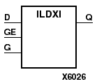
ILDXI is a transparent data latch, which can hold transient data entering a chip. When the gate input (G) is High, data on the input (D) appears on the output (Q). Data on the D input during the High-to-Low G transition is stored in the latch.
The latch is asynchronously preset, output High, when power is applied. FPGAs simulate power-on when global set/reset (GSR) is active. GSR defaults to active-High but can be inverted by adding an inverter in front of the GSR input of the STARTUP, STARTUP_SPARTAN2, or STARTUP_VIRTEX symbol.
The ILDXI is actually the input flip-flop master latch. Two different outputs can be accessed from the input flip-flop: one that responds to the level of the clock signal and another that responds to an edge of the clock signal. When using both outputs from the same input flip-flop, a transparent High latch (ILDXI) corresponds to a falling edge-triggered flip-flop (IFDXI_1). Similarly, a transparent Low latch (ILDXI_1) corresponds to a rising edge-triggered flip-flop (IFDXI). Refer to the following figure for legal IFDXI, IFDXI_1, ILDXI, and ILDXI_1 combinations.
| Inputs | Outputs | ||
|---|---|---|---|
| GE | G | D | Q |
| 0 | X | X | No Chg |
| 1 | 0 | X | No Chg |
| 1 | 1 | 1 | 1 |
| 1 | 1 | 0 | 0 |
| 1 | D | d | |
| d = state of referenced input one setup time prior to High-to-Low gate transition | |||